Network two-in-one surge protector

Network two-in-one surge protector
Features
●The product adopts series structure design with multi-level protection function
●Large discharge current, fast response, low loss
●The signal part adopts the electronic switch grounding method, which can effectively eliminate various interferences caused by the common ground to the transmission signal
●Energy saving, environmental protection, low residual pressure and long service life.
●Integrated combination, small size, simple wiring, convenient installation, strong practicability
The LH-RJ485 control signal lightning protector is used to protect sensitive high-speecommunication network lines from damage caused by lightning induced voltage, powerinterference, electrostatic discharge, etc. The signal lightning protection device adopts multi-level protection circuit, selects world-famous components, and is manufactured by advanced production technology. It has the characteristics of large current capacity, low residual voltage level, sensitive response, stable performance, and reliable operation.
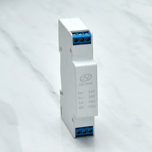
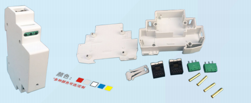
Network two-in-one surge protector accessories
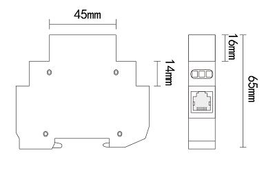
Product Size
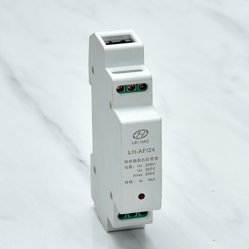
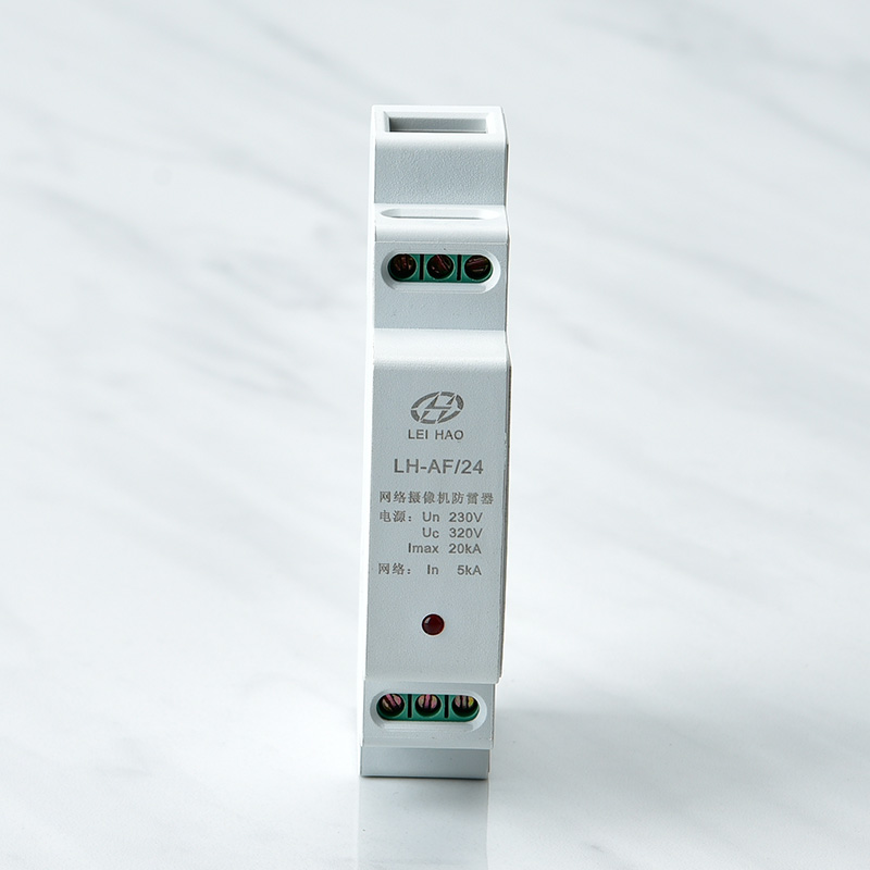
Technical Parameters
|
Model |
LH-AF/12 |
LH-AF/24 |
LH-AF/220 |
Net |
|
Maximum continuous working voltage Uc |
12V~/- |
25V~/- |
250V~/- |
6V- |
|
Maximum continuous working current Un |
3A |
3A |
3A |
———— |
|
Nominal discharge current (8/20) In |
1KA |
3KA |
3KA |
3KA |
|
Protection voltage Up |
≤160V(line/line) |
≤200V (line/line) |
≤1300V (line/line) |
≤10V (line/line) |
|
≤600V (line/PE) |
≤700V(Line/PE) |
≤1500V(Line/PE) |
≤450V(Line/PE) |
|
|
Response time tA |
≤25ns (line/line) |
≤1ns (line/line) |
||
|
≤100ns (line/PE) |
≤100ns (line/PE) |
|||
|
Data transmission rate Vs |
———— |
100Mbit/s |
||
|
Interface method |
5.0mm pitch terminal |
RJ45 |
||
|
Wiring specifications |
0.5m² ~1.5m² |
———— |
||
|
Working temperature zone |
-40 ℃~+80℃ |
|||
|
Shell material |
Flame retardant plastic |
|||
|
Shell protection level |
IP20 |
|||
|
Size |
1 standard module |
|||
|
Mounting brackets |
35mm electrical rail |
|||
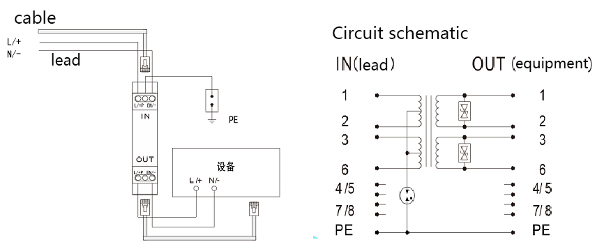
Installation and maintenance
1. The lightning protection device is connected in series between the protected equipment and the signal channel.
2. The input terminal (IN) of the lightning arrester is connected to the signal channel, and the output terminal (OUT) is connected to the input terminal of the protected equipment, and cannot be reversed.
3. Reliably connect the ground wire of the lightning protection device with the ground wire of the lightning protection system.
4. This product does not require special maintenance. When the lightning protection device is suspected to be malfunctioning, the lightning protection device can be removed and thenchecked. If the system returns to normal after the system is restored to the state before use, the lightning protection device should be replaced.


●The power supply must be cut off before installation, and live operation is strictly prohibited.
●Please select the product with the same interface type as the protected equipment
●The anti-demand device should be wired four-wire with the working voltage of the protected equipment
●Lightning protection device: “L/+” of the power line is live/positive, and “N/-” is zero/negative
●The PE wire of the lightning protection device must be reliably connected to the ground wire of the Sree system.
●When installing, please connect as shown in the installation diagram, where N is input, OUT is output, PE is ground wire, input terminal is connected to external wire, output terminal is connected to the input terminal of the protected equipment, and do not connect wrongly.
●The power supply part of the lightning protector has work instructions. When the power is turned on and the work indicator is on, it means that the power is normally connected and the lightning protection components are working normally; on the contrary, the lightning protection device cannot be used and should be repaired or replaced in time.
●The PE wire of the lightning protection device must be reliably connected to the ground wire of the lightning protection system, and the connection wire must be short, thick, and straight.
●The lightning arrester should be tested regularly during its use. If it fails, it should be repaired or replaced in time to ensure the safety of the equipment.